

Scientific Article by Lecturer Dr. Abdullah Jabbar Al - Gharani High–strain dynamic testing for concrete column
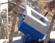
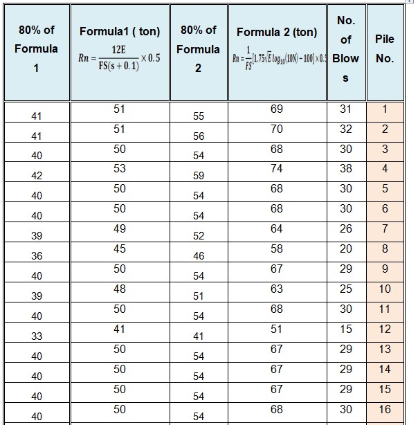
The testing can be executed by either static or dynamic test however, the static procedure takes long time in case of large numbers of column piles in wwtp or wtp project. This testing could be carried out by two method as follows:<br />A) High strain Dynamic testing and analysis using the column Pile Driving Analyzer, PDA-PAX. According to ASTM D4945 Method. <br />B) Dynamic column pile testing and analysis depending on hammer machine energy and number of blows at last 250 mm of each pile using dynamic formulas of Design Specifications.<br />THE COLUMN DRIVING ANALYZER, PDA-PAX:<br />This system of testing to determine pile capacity is being used in more than 40 countries including U.K., Canada, Germany , Sweden, Australia, India, China, Singapore, etc. It has been incorporated in several codes worldwide and has been routinely used as a supplement or substitute to static load testing. To mention prominently would be ASTM D4945 and Institute of Engineers Code, TTL Publications, U.K. The tests has been carried out on 12 precast concrete piles of ( 285 x 285 mm.) which represent the working driven piles in the project sites and structures.<br />TEST EQUIPMENT: <br />A column Pile Driving Analyzer R-Model PAX and its associated pile top force and velocity transducers were used to conduct the dynamic pile test. Two strain transducers and two accelerometers were attached to the pile head. They were mounted on opposite sides of the pile to cancel bending effects during each strike of the hammer. The signals of strain and acceleration were conditioned and processed by PDA. The PDA is a micro-processor based signal conditioner and digital computer. Signals of pile top force and velocity were measured and analyzed during each strike of the pile driving hammer Fig.1 and stored in the Analyzer. The pile top force and velocity-time curves were displayed on laptop computer screen. Real time analogue signals of the pile top force and velocity were also recorded using the PDA and later stored in the field computer unit. <br /> The PDA onsite uses a program based on closed form Case-Goble solutions to compute static pile capacity from the pile top force and velocity data. This is subsequently checked with the computer program CAPWAP to confirm the static pile capacity obtained on site. Fig.2 represent the concrete column testing.<br /> COLUMN PILE MONITORING AND PREPARATION:<br />a) High-Strain Dynamic Testing of piles is conducted by attaching strain transducers and accelerometers to the sides of the pile approximately 1 to 1.5 times pile Dia. below the pile top Fig.3. These pairs of gauges are fixed onto opposite sides of the pile so as to detect bending in the pile if any during testing. <br />b) These transducers are then connected through the main cable to a Pile Driving Analyzer, which is a State of Art Pentium Computer System with ability to record strain and acceleration measurements and convert them from analog to digital form. <br />c) The signals are then triggered by the impact of a ram falling from a pre-determined height. The ram weight and fall height is determined in advance. As a thumb nulled, the ram weight shall be 10% to 1.5% of the testing capacity of the pile. Thus for measuring a 500 ton load, the ram weight shall be approximately 5 tons. <br />d) Upon impact, the strain transducers measure strains whereas accelerations are measured by accelerometers connected on either sides of the pile. These signals are then converted to digital form by the Pile Driving Analyzer and then converted to force and velocity respectively by integration. <br />e) The capacity mobilized under the blow is then obtained from the force and velocity values. The PDA has an in-built program which calculates and generates over 30 pile variables based on pile top force, displacement and velocity. Immediate field results in the form of the capacity of the pile, pile top settlement etc., integrity and stresses developed in the pile etc. are obtained. <br />PDA FIELD TESTING AND RESULTS: Dynamic testing on the column piles was conducted by striking the piles ten blows during the re-striking process. During testing of the 12 column piles. The PDA measures the total (static plus dynamic) resistance acting on the pile. The portion of total resistance that is computed as static resistance by the Analyzer Fig.3 is determined by the soil damping factor Jc set into the analyzer. A more accurate independent measure of the applicable soil damping factor was determined using a CAPWAP analysis.<br />DATA PROCESSING AND ANALYSIS: <br />a) Under each hammer blow, the column Pile Driving Analyzer is triggered and data acquisition begins at this time. The PDA automatically processes each blow recorded during monitoring and can display computed values of over 30 column pile variables on command. The capacity of the column pile is immediately indicated at the end of the field testing. This is then verified with the Case Pile Wave Equation Analysis Program (CAPWAP) for a typical blow. <br />b) The CAPWAP program is an analytical method that combines measured field data with pile wave equation type procedures, to predict the pile's static bearing capacity and soil resistance distribution. Measured force and velocity data is directly input from the PDA. Based on the measured velocity data, the program computes force required to induce the imposed velocity. Both measured and computed forces are plotted as a function of time and the iterative analysis is continued till good agreement between both the curves are reached. If the agreement is not satisfactory, the soil resistances at the pile point and along the pile are adjusted until a good match is obtained. This gives better estimates of the actual static pile capacity measured during field testing, and also the friction and end bearing components. <br />c) The PDA and subsequent CAPWAP analysis indicate the amount of static capacity that is actually mobilized during any blow delivered to the pile during testing. In order to fully mobilize pile static capacity, a pile set in excess of 3-4mm per blow is required. Should the pile set be less than 3-4mm, then not all the static pile resistance will be mobilized during any one blow and the subsequent CAPWAP and PDA analysis will under predict the ultimate static capacity of the pi le. In other words, the ultimate capacity of the pile will be still higher than that indicated after field testing/CAPWAP analysis. This provided some in-built conservatism to the capacities indicated by the PDA and CAPWAP system in the event of small set being recorded. <br />CAPWAP ANALYSIS: <br />A selected PDA field recording of force and velocity data for a blow delivered to the piles was further analyzed using the CAPWAP (Case Pile Wave Analysis Program) computer software. The analysis involved applying the measured pile top velocity time record to the top of a lumped-mass and spring wave equation model of the pile. <br />The program computes the pile top force-time record and this is then compared to the actual measured force-time record. The pile and soil resistance model is then adjusted in an iterative procedure until good match is obtained between measured and computed forces. The pile and soil models can then be used to determine the estimated static load-settlement curve.<br />THE RESULTS OF TESTS :<br /> From the results and records obtained from CAPWAP computer software analysis the next table represent final results of ultimate and allowable bearing capacity with safety factor equal to (2) for tested column piles with its settlement :<br />It is very clear that as the settlement decrease the working bearing capacity increase. <br />Dynamic pile testing and analysis depending on hammer machine energy and number of blows. The testing method was depending on hammer machine energy and number of blows at last 250 mm of each pile using dynamic formulas.<br />COLUMN PILE-DRIVING FORMULAS: <br />Several equations have been developed to calculate the ultimate capacity of a pile during driving. These dynamic equations are widely used in the field to determine whether the pile as reached satisfactory bearing value at the predetermined depth. One of the earliest of these dynamic equations commonly referred to as the Engineering News Record (ENR) formula-is derived from the work-energy theory. This formula is<br /> <br />where:<br />Rn= nominal pile resistance measured during pile driving (ton)<br />FS= Factor of safety, FS =6 was recommended to estimate the allowable pile capacity if (ENR) formula is used.<br />E= developed hammer energy (lbs.)<br />s= pile permanent set, (in/blow)<br /> s, is usually based on the average value obtained from the last few driving blows.<br />The other used formula for the prediction of pile capacity is the FHWA Gates Formula. The nominal pile resistance as measured during driving using this method shall be taken as:<br /> <br />where:<br />Rn= nominal pile resistance measured during pile<br />driving (ton)<br />FS= Factor of safety =3 was recommended to estimate the allowable Column pile capacity.<br />E= developed hammer energy (lbs).<br />N= Number of hammer blows per (1in) of pile permanent set.<br /><br />ASSUMPTIONS:<br />Both of the pervious dynamic formulas depend on the energy of the hammer, or the weight of hammer(Mitsubishi MH-35) multiplied by the distance moved through the stroke, then the necessary data were taken from the reference " Construction Equipment Guide" by David A. Day, Neal B. H. Benjamin. The specifications of Mitsubishi MH-35 was found to be as follows:<br />The minimum energy of (38600 ft-lb) was used in the calculations of the working pile capacity.<br />The following efficiencies for hammer types were used to find the final value of pile capacity. The values in the table depends on the type of the hammer. The MH-35 is a diesel hummer type therefor, an efficiency factor of 0.8 will be used.<br />By using equations 1 and 2 a sample of calculations are listed:<br />CONCLUSION: <br />According to the results of working bearing capacity obtained from the two methods used in this report and compare it with the design working bearing capacity (30 Ton) for every column pile it was found that all piles had working bearing capacity more than 30 ton. And it successes in the tests . <br /><br /><br />